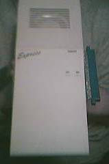
Picture showing the whole unit. Please note, the edge connector in this picture has been replaced
| Expansion Systems: Dataflyer Express |
| Anschluss: Seitlicher Expansion Slot |
Picture showing the whole unit. Please note, the edge connector in this picture has been replaced
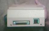
Picture showing the rear of the unit showing the DB25 SCSI Connector and Power Connector
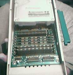
Picture showing inside the unit
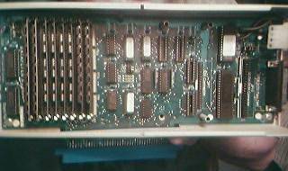
Chips, labelled from left to right (in middle of board) DECODE 1.0 (in socket U14) RASCAS 1.0 (in socket U15) DFS PAL (in socket U16)
Dataflyer Express Diagrams - bytes
(far right of board) DF AUTOBOOT VERSION 2.0 (in socket U24) -- this version shipped with original Express models. (Could be upgraded with the version 2.1 TT chip used in later DF 500 models as well -- this ROM is on board)
The controller chip below the autoboot ROM is made by AMD.
The pictures show the SCSI only version of this unit, but the three empty slots on the board are for adding the IDE controller
The Dataflyer Express came in three different flavours, IDE Only, SCSI Only and both IDE and SCSI. It also had 8 x 30pin SIMM sockets for up to 8MB of additional RAM and could accept both 1MB and 256k SIMMs. The SIMMs must be added in pairs. The unit PCB itself may have been simply a Zorro II card fitted in the a box designed to fit the expansion socket of the A500 using the female edge connector, because it could be removed and placed in an A2000. The Dataflyer Express would also take advantage of the Baseboard if it was installed.
| Einsendungen zu dieser Seite von: Christopher Smith |
Einem link gefolgt? Hier gehts zur Hauptseite
Followed a link? Please go to the Main Site