A2000
| Commodore: A2000 |
| Anschluss: Andere |
A2000
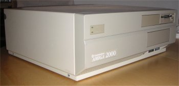
A2000, Side view
A2000 inside view - bytes
Hi Res Version, A2000 - bytes
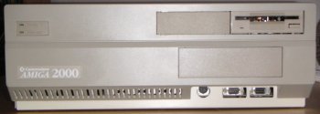
A2000 backside view - bytes
A2000 front view - bytes
Hi Res Version, A2000, Side view - bytes
Image of A2000 with case off - bytes
Hi Res Version, A2000 US Keyboard, Front - bytes
HiRes Version A2000(A) mit schwedischer/finnischer Tastatur - bytes
Hi Res Version, A2000 US Keyboard, Rear - bytes
A2000 Revision 4.0 Motherboard - bytes
A2000 Revision 4.0 Motherboard, Image 2 - bytes
A2000 Rev. 4.1 Motherboard - bytes
A2000 Rev. 4.3 Motherboard - bytes
A2000 Rev. 5.0 Motherboard, unbestueckt - bytes
A2000 Revision 6.2 Motherboard, Green PCB - bytes
A2000 Revision 6.2 Motherboard, Brown PCB (Most chips missing) - bytes
A2000 Revision 6.2 Motherboard, ROM Closeup - bytes
Buster Tower - bytes
A2000 Revision 6.4 Motherboard - bytes
A2000 Revision 6.4 Motherboard, Closeup (Bottom Right) - bytes
A2000 Revision 6.4 Motherboard, Closeup (Top Right) - bytes
A2000 Revision 6.3 Motherboard - bytes
A2000 Revision 6.4 Motherboard, Closeup (Bottom Left) - bytes
A2000 Revision 6.3 Motherboard, Buster - bytes
A2000 Revision 6.3 Motherboard, Paula and Denise - bytes
A2000 Revision 6.4 Motherboard, Closeup (Top Left) - bytes
A2000 Revision 6.3 Motherboard, Gary - bytes
A2000 Revision 6.3 Motherboard, CIAs - bytes
A2000 Revision 6.3 Motherboard, chipset overview - bytes
A2000 Revision 6.3 Motherboard, Processor - bytes
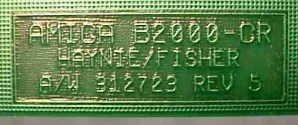
A2000 Revision 6.3 Motherboard, engineering label - bytes
A2000 Revision 6.3 Motherboard, assembly label - bytes
Download A2000 Model B Schematics - bytes
Standard Specifications
| Case Type: | Desktop |
| Processor: | 68000@7.14Mhz |
| MMU: | None |
| FPU: | None |
| Chipset: | OCS (for KS 1.1 - 1.3 models) or ECS (KS 2.04 models) |
| Kickstarts: | V1.1 V1.2 (Model A) V1.3 (Model A & B) V2.04 (Model C) |
| Bus Controller: | None (German Model-As) Buster Rev 1 Buster Rev 2 Buster Rev 3 |
| Expansion Slots: | 5 x 100pin Zorro II slots 1 x Genlock slot (Model A only) 1 x OCS/ECS Video Slot (NOT inline with Zorro, Model B & C only) 2 x inactive 16bit ISA slots (inline with Zorro) 2 x inactive 8bit ISA slots (NOT inline with Zorro) 1 x 86pin CPU Fast Slot (limited functionality on Model A) |
| Standard CHIP RAM: | 512K (Rev 3.x/4.x/5.x) 1MB (Rev 6.x) |
| RAM sockets: | None |
| Hard Drive Controllers: | None |
| Drive Bays: | 2 x 3.5" (with faceplates) 1 x 5.25" (with faceplate) |
| Expansion Ports: | 1 x 25pin Serial 1 x 25pin Parallel 1 x 23pin RGB Video 1 x 23pin External Floppy 2 x 9pin Joystick/Mouse 2 x RCA Audio (Left/Right) 1 x RCA Composite (Models B & C only) 1 x large 5pin DIN Keyboard Connector |
| Floppy Drive: | 1 x 3.5" Internal 880K Floppy Drive |
| Motherboard Revisions: | Model A (German design): Rev. 3.0 (pre-production version) Rev. 3.8 (pre-production version) Rev. 3.9 (pre-production version) Rev. 4.0 (production version)
Model B (US design):
Model C (US Design. The term "A2000-C" was invented by the community) |
| Battery Backed Up Clock: | Yes. Model A used square varta batteries, Model B & C uses "barrel" shaped batteries. |
The A2000 was launched in 1986 and was aimed at the professional productivity market. The original version was designed in germany, and was actually based on the the A1000, not the A500. However, later that year Commodore US redesigned it, and the new model (referred to as A2000-B) was indeed the high-end version of the A500 that the A2000 is known as. There are probably more variations and revisions of this model than any other Amiga. Not only were at least 15 separate motherboard revisions produced, the model spans 3 versions of Kickstart and two chipset generations. Several sub-models (A1500, A2000HD and A2500) were also produced. It is usually possible to tell the difference between the OCS and ECS versions of the A2000 by the colour of the front panel LEDs. The OCS versions have a red power LED and a green HD LED, while the ECS versions have a green power LED and an orange HD LED. The easiest way to separate an A2000-A (the A1000-based german version) from the later, A500-based models, is to see if there is a composite connector beside the RCA sound connectors at the back. If there is none, it's the original version. All Amiga 2000s were sold with 1MB of RAM, but how this was implemented varied over motherboard revisions. The German (model A) designs have 512K chip RAM on the motherboard and 512K Fast RAM on an expansion card fitted to the CPU Fast slot. The US 4.x (model B) motherboards had 1MB of RAM soldered to the motherboard with 512K configured as CHIP RAM and 512K as Fast. The Fast RAM on these models can be reconfigured into Chip RAM by upgrading the Agnus and cutting some connections). Rev 6.x ("model C") boards have 1MB of RAM soldered to the motherboard, all of which is configured as CHIP RAM.
Early A2000's were fitted with a Buster Tower which sits in the buster socket. This is because the buster was faulty, it was missing a term signal in one of the backplane buffer control signals. The tower contained an additional PAL which fixed this problem.
Motherboard revisions according to Dave Haynie (Commodore Engineer)
"The A2000 Model A was a german design, like an A1000 in a different box. 512K CHIP and non-standard processor and video slots. Yes, The orginal A2000 was designed in Germany. It was based on an integration of the A1000 motherboard design and the example Zorro II backplane from "Schematics and Expansion Specifications", the A1000 hardware manual. It used the thin Agnus, which handled only 512K of DRAM. They added a "Genlock" slot, which was essentially just the 23-bit video signals on an internal connector, and the "MMU" slot, which was essentially just the A1000 external edge connector on an internal slot. The machine shipped with 512K of Fast RAM in this slot, though the case was slow and had some reliability problems. About 60,000 of these machines were made, so I've heard.
A2000-B Redesigning The German Model:
This was the original A2000-CR (Cost Reduced) that I designed. I took the A500 chip set and integrated most of the control logic for the expansion bus into a gate array called Buster (the original thin Buster). This board was code-named the "B2000", not out of any special letter-sequencing, but because it was made from some A500 parts -- the A500's code-name was the "B-52".
To the German design, I added a second video connector, which brought out the remaining 8-bits of digital the video signal and some parallel port lines (just in case someone needed a way to control something out there). I also designed a "coprocessor interface" for the internal CPU slot, which allowed processor cards to be added without the need to remove the 68000. And of course, given the much higher integration (thanks due to Buster, Gary, Fat Agnus, etc), I was able to fit 1MB of RAM on the motherboard, even though I went to a 2-layer board (management's demands for cost, not my idea, though I did make it work OK.)
REV 3.9:
About 200 pre-production B2000s were released, as "Dealer Demo" units, never meant to be sold. That's labelled Rev 3.9, of course some dealers sold them, since the A2000 was hot. These may have problems with CPU slot devices since, like the orginal A2000, there was no additional buffering on the clocks that drove that slot (and timing is very critical in many CPU slot applications).
REV 4.x Series:
The Rev 4 A2000 was around most of the system's life. This was really just the Rev 3.9 with all the finalized changes. Extra buffering splits Agnus clocks between internal, expansion, and CPU slots. Rev 4.1 immediately corrected one missing signal on the secondary video slot (no plain Rev 4.0 boards were released). Rev 4.2 was some kind of production fix, I think it removed some overzealous FCC hacks, like the extra filter capacitors on the keyboard connector. Rev 4.3 tweaked a few pullup resistor values, to adjust for differences in the new CSG-made Gary chip (a full custom part) versus the Toshiba-made Gary chip (a gate array). After some 150,000 or so A500/A2000s, the CSG Gary was phased in. Rev 4.4 I believe made some changes to filtering of the TICK line, to account for some new power supplies that had been particularly noisy on that line. Rev 4.5 increases the value of the pullup resistor on the BAS* line of the expansion bus; there was a strange problem in conjunction with expansion bus DMA turnaround (what happens after a DMA device gives the bus back), BAS*, certain vendors of the 74ALS245 buffer that sits between BAS* and the local bus's AS*, and accelerator cards that could cause crashes. Add a 1K or so pullup to pins 11 and 20 of U605 on pre-4.5 boards to fix this problem (this was the only severe problem addressed by any subrevision).
REV 6.x Series:
The Rev 6 A2000 was never called the A2000C, except maybe by geeks on usenet :-).
The Rev 6 A2000 changed the DRAM array from 256K x 1 parts to 256K x 4 parts. Some layout and FCC changes were made, I don't know just what, I was kind of out of the picture at the time (Rev 5 was just Rev 4.5 with the DRAM changes, nothing else. Rev 6 did more, I wasn't really involved). The original Rev 6 board has some noise problems on the expansion bus, possibly due to a new production of 68000s from Motorola that happed to be used at the same time. Rev 6 also had some extra noise on its time-of-day clock. Rev 6.1 corrects the clock noise, Rev 6.2 addresses the expansion bus noise.
A2000 Rev 5
While there are many Amiga 2000s in the world, the Rev 5 is extremely rare. As far as I know, only about five boards were made. The purpose of the Rev 5 board was simply to add higher density memory to the Amiga 2000. The original design used sixteen memories for a bank of memory, this design used four (there are two banks). This was the last Amiga 2000 motherboard I had all that much to do with..
At the time, the Rev 4.x was in production, and the new board was desired for new production, as the price crossover from the 256K x 1 to the 256K x 4 memories had been reached. However, the Rev 5 board was completed ahead of the need for it. So the PCB guys did some additional cleanup work on the design, and I think the FCC people got involved, too. Regardless, the resulting Rev 6 motherboards were plagued with problems (in fairness, some were due to the switchover to a 68000 with faster signals, that was also noisier). - Dave Haynie
Additional
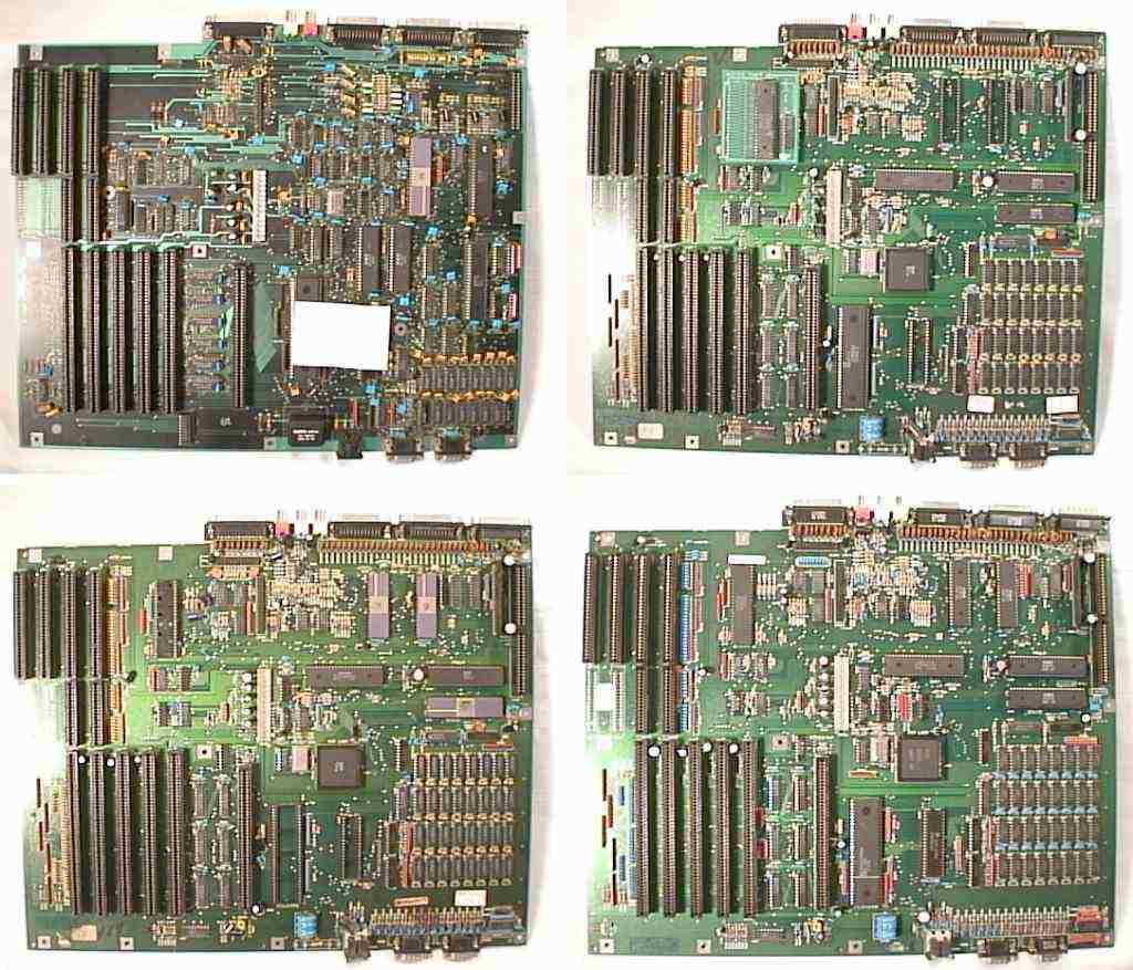
"This first motherboard is a Rev 4 German Amiga 2000 motherboard. This is the one based on the original A1000 logic, not the A500 logic. It supports only 512K of on-board memory, and the CPU slot is limited in function. This board appears to be in good physical order, though it hasn't been tested. There is a note attached:
Works Good!! Thanks FYI: Board has same 1 <-> 31 swap as early A500's -Bryce
Apparently a note from Bryce Nesbitt. The "1 <->31 swap" was for pin numbers on the ROM. Commodore has apparently received bogus information about which pin would supply the next address line, as these ROMs grew from 256K to 512K. The German A2000 and some early A500s had this problem, as the note says. The correct information prevented this issue in US Amiga 2000s.
The board on the top right is a US "B2000" Rev 3.8 (preproduction) Amiga 2000. This has been stripped of its ROM and its 8520s, but it does include the Buster "Tower". That tower's my fault, lemme 'splain. When I took over the Amiga 2000 project, in the fall of 1986 (well, after the shock wore off), I set out to implement the first "Buster" (Bus controller) chip. This did with the expansion logic much of what Gary and the Fat Agnus did to the original Amiga 1000 logic: shrunk it in price and in size. Since I was, in essence, copying the German design (they _do_ look similar, eh), I took the PAL equations from the Amiga 2000 on the left as my basis for the Buster chip.
Whoops. There was a bug in the German PALs. There are a set of buffers between the A2000's local bus (directly on the 68000) and the Zorro bus. When a Zorro bus master talks to a Zorro bus target, these buffers are supposed to point away from Zorro, toward the local bus. During pre-production testing at the Commodore plant in Taiwan, I discovered that wasn't the case with the German A2000, or my shiny new Buster chip -- motherboard buffers fought with anything driving the expansion bus in this case. Whoops.
In Germany, they fixed it with a new PAL. The Buster "tower" fixed it here, until a corrected Buster chip could be produced.
The board on the bottom left is another "B2000" Rev 3.8 board. This one still has those precious 8520s, but it has been stripped of the 68000, the ROM, and any sort of Buster chip. All A2000 Busters do work in all motherboards, you don't need a towered Buster for these older boards. However, the Rev 3.8 board was questionable with CPU cards -- the primary reasons for Rev 4 were FCC issues and beefing up the whole coprocessor mechanism with additional buffers.
This final board is a "B2000" Rev 4.3 motherboard, often considered the first "golden" version of the Amiga 2000." - Dave Haynie
Jumpers
These setting come out of the manual for an Amiga 2000 Revision 4.x and is compliant with Rev 6.x Amiga 2000 boards as well.
| Einsendungen zu dieser Seite von: Christian Buker, Dave Haynie, Gerhard Kupka, Greg Scott (National Amiga), Holger Hesselbarth, Joe Thomas, RiWa & Friends, Sylvio Kurze, Takahasi Kasiko, Varga Gabor |
Einem link gefolgt? Hier gehts zur Hauptseite
Followed a link? Please go to the Main Site